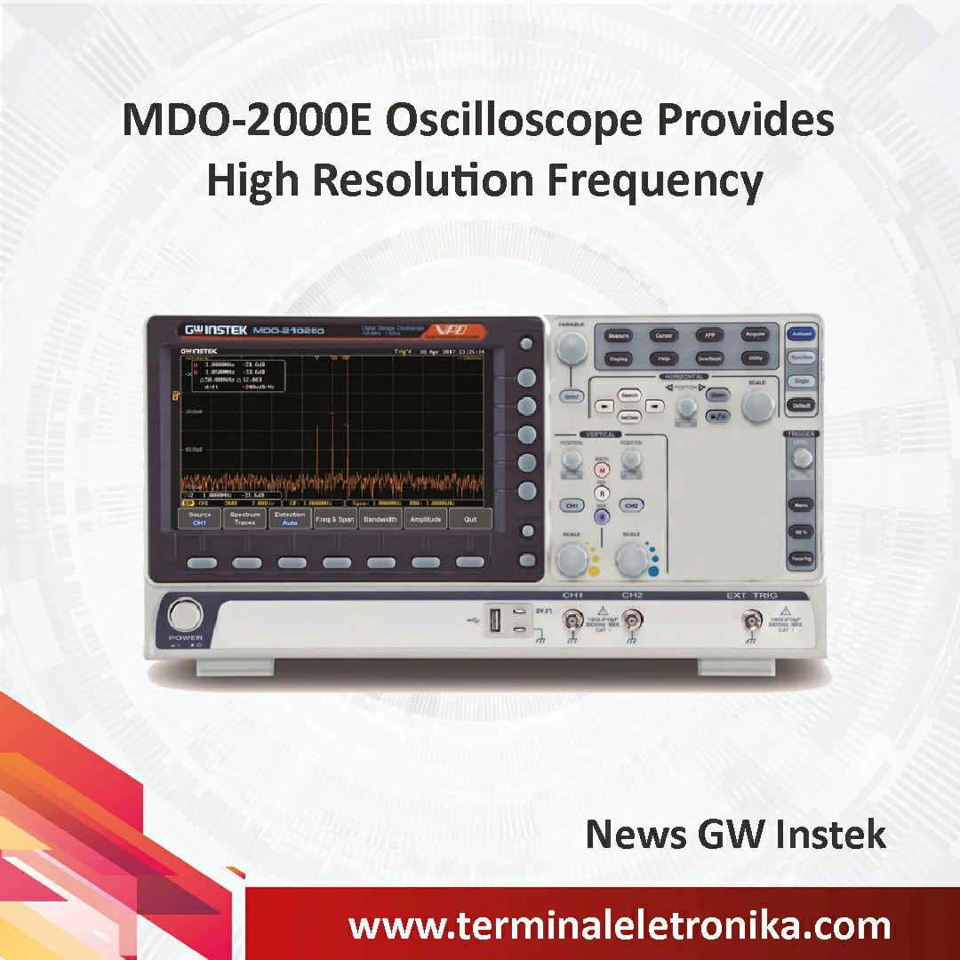
For electronics engineers or students of related academic departments, there should be more opportunities to use the oscilloscope. However, for the requirement of the spectrum distribution of the signal in the frequency domain, the expensive spectrum analyzer is not as popular as the oscilloscope. When oscilloscope’s FFT function is used, its operation speed will be limited by the number of FFT points and the computing power of the CPU. The frequency domain resolution is limited by the number of FFT points and the sampling frequency, and the FFT is difficult to adjust, so most of the tests cannot satisfy the requirements.
From the schematic on the right, we can see how the FFT function of the oscilloscope and the spectrum analyzer test differ in the frequency domain test. The spectrum analyzer can set the start frequency, stop frequency, center frequency, Span and RBW parameters according to the frequency of the test to provide users with a better frequency domain resolution.

For users who have not used a spectrum analyzer before, the parameters on the spectrum analyzer could be unfamiliar. The following instructions will let you know the relationship among the parameters to allow you to quickly and correctly set up the spectrum analyzer in the actual test.
1. Span= (Stop frequency)-(Start frequency)
2. (Start frequency)+(Stop frequency) /2 =Center frequency
3. RBW=Sample rate/length of FFT.
The recommended setting steps are as follows:
1. Before testing an unknown signal, observe the frequency of the main waveform from the oscilloscope's frequency counter. The center frequency of the spectrum analyzer can be set by this frequency.
2. The center frequency = (Start frequency) + (Stop frequency) /2. Use this reference to set the Start frequency and Stop frequency to allow the frequency domain waveform to be displayed on the screen.
3. Set Span: RBW. The measurement speed in the frequency domain depends on Span: RBW. The higher the ratio, the more the scanning points, hence, the slower the update rate.
The following is an example of testing the FSK modulation waveform:
A. Use the oscilloscope frequency counter to learn the main frequency of this signal to be tested.

B. Set the center frequency of the Spectrum Analyzer by this frequency; set the start and stop frequencies to clearly observe the changing waveform of the FSK in the frequency domain.

C. Use the search function to find Max.peak to clearly display the measurement data.

When the same signal is tested by FFT, for most users, the correlation between the sampling rate of the time domain signal and the frequency of the DUT signal is not known, so the FFT waveform display is not easy to adjust correctly. Furthermore, the slow update rate, time domain waveform overlapping with the frequency domain waveform, and most of the FFT do not provide the search function together make FFT impossible to clearly analyze the frequency domain waveform and to simultaneously measure the components of the modulated signal. The FFT without RBW setting does not allow users to adjust the output waveform with the best resolution based upon the characteristics of the actual waveform.

To sum up, the Spectrum Analyzer function of MDO-2000E provides better frequency domain resolution comparing with the FFT of general oscilloscopes. MDO-2000E is a suitable choice for basic frequency domain tests and academic courses.
